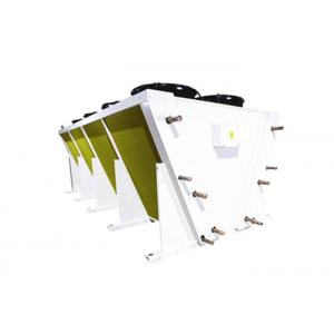
Industrial Forced Convection Liquid Cooler For Power Generation Process Cooling
Features
High efficiency heat exchanger: capacity designs for maximizing the heat transfer relative to the energy consumption of the fan. Tube and tube coupling design for low pressure drop in the coil on the media sides(maximum 100KPa at water designing condition). Our thermodynamic and aerodynamic designing software is long year tested and proved in Germany. Fan: only choose low specific energy consumption fans. Fan nozzle designs for maximum air flow and air throw.Our fans from the world`s leading manufacturer are practically proved to be reliable in operation and long lasting. Motor: protection class IP 54 and insulation class F. Air separator for each fan. We facilitate you to have a long lasting and low maintainance operation. Durable material and rigid enclosure with hard gloss powder coated finish. Protective enclosure for both manifolds and U-bends. Unit design for outdoor installation. 100% leakage tested at 31bar.
Options
A. Coil design refrigerant: water, oil, glycol.
B. Multiple circuits.
C. Sub-cooling circuits.
D. Stainless steel or aluminum casing.
E. Coated aluminum or copper fins.
F. Explosion proof motor.
G. Customized fin spacing.
Technical parameter
Liquid dry cooler D1 series parameter(fin space 2.1mm)
| Type |
D1-005-
1x350
|
D1-006-
1x350
|
D1-007-
1x350
|
D1-009-
1x450
|
D1-011-
1x450
|
D1-013-
1x450
|
D1-014-
1x500
|
D1-017-
1x500
|
D1-020-
1x500
|
| Capacity |
Water |
35℃ outdoor temp. |
Inlet |
45℃, |
△ |
KW |
4.89 |
5.9 |
6.83 |
9.39 |
10.99 |
13.33 |
14.32 |
17.01 |
19.8 |
| outlet |
40℃ |
Y |
| 20% Glycol |
Inlet |
45℃ |
△ |
4.72 |
5.69 |
6.69 |
8.9 |
10.61 |
13.05 |
13.91 |
16.11 |
19.29 |
| outlet |
40℃ |
Y |
| Medium |
Water flow |
M3/h |
0.85 |
1.03 |
1.2 |
1.63 |
1.91 |
2.3 |
2.5 |
3 |
3.5 |
| Pressure drop |
kPa |
36 |
31 |
58 |
25 |
40 |
80 |
50 |
60 |
40 |
| Air flow |
△ |
M3/h |
2828 |
2712 |
2492 |
6199 |
5827 |
5225 |
8469 |
8168 |
7601 |
| Y |
| Fan motor |
Phase |
1 |
1 |
1 |
3 |
3 |
3 |
3 |
3 |
3 |
| △ |
W |
140 |
140 |
140 |
540 |
540 |
540 |
830 |
830 |
830 |
| Y |
| △ |
A |
0.6 |
0.6 |
0.6 |
1.1 |
1.1 |
1.1 |
1.45 |
1.45 |
1.45 |
| Y |
| Fan |
No X φ |
1x1x350 |
1x1x350 |
1x1x350 |
1x1x450 |
1x1x450 |
1x1x450 |
1x1x500 |
1x1x500 |
1x1x500 |
| Sound pressure level |
△ |
dB(A) |
31 |
31 |
31 |
43 |
43 |
43 |
49 |
49 |
49 |
| Y |
10m |
| Dimension |
L |
mm |
870 |
870 |
870 |
1020 |
1020 |
1020 |
1220 |
1220 |
1220 |
| W |
mm |
525 |
525 |
525 |
625 |
625 |
625 |
825 |
825 |
825 |
| H |
mm |
797 |
797 |
797 |
820 |
820 |
820 |
870 |
870 |
870 |
| A |
mm |
690 |
690 |
690 |
840 |
840 |
840 |
1040 |
1040 |
1040 |
| B |
mm |
-- |
-- |
-- |
-- |
-- |
-- |
-- |
-- |
-- |
| C |
mm |
-- |
-- |
-- |
-- |
-- |
-- |
-- |
-- |
-- |
| D |
mm |
490 |
490 |
490 |
490 |
490 |
490 |
490 |
490 |
490 |
| Inlet φ |
mm |
3/4” |
3/4” |
3/4” |
1” |
1” |
1” |
1-1/4” |
1-1/4” |
1-1/4” |
| Inlet φ |
mm |
3/4” |
3/4” |
3/4” |
1” |
1” |
1” |
1-1/4” |
1-1/4” |
1-1/4” |
| Product weight(empty) |
kg |
38 |
42 |
48 |
55 |
60 |
67 |
75 |
82 |
91 |
Application in power industry:
Engine cooling(gas, biogas, siesel, HFO...0
Cogeneration/ORC/Waste to Energy Power plants
HVDC(High Voltage Direct Current)
TAIC cooling(Turbine Air Inlet Cooling)
Geothermal plants
Solar thermodynamic plants
Application in process industry:
Chemical and pharmaceutical industries
Air/Gas compressor cooling stations.
Industrial processes cooling (steel/plastic/glass/cement plants)
Automotive industry
Data centres
Oil & Gas:
oil and gas industry